T S Diagram Of An Invisid Pump Turbine Brayton Compressor Cy
T-shaped equivalent diagram of centrifugal pump Solved using the t-s diagram for water/steam (fig. a-9) T s диаграмма воздуха
Draw A Schematic Diagram Of A Heat Engine
Draw the t-s diagram for the schematic below:and no, Design of vapor-compression refrigeration cycles Using a temperature-entropy diagram for water
T-s diagram of heat pump cycle[6]. t-s diagram of heat pump cycle is
Explaining rankine cycle in an easySolved problem 6.023 si the figure below provides the t-s T-s diagram with open feed water heaterResco site analysis project.
Turbine engine thermodynamic cycleWolfram diagram water entropy temperature demonstrations Design of vapor-compression refrigeration cyclesDiagram steam ts water entropy temperature chart h2o.
![[DIAGRAM] T S Diagram Steam Pdf - MYDIAGRAM.ONLINE](https://i2.wp.com/d2vlcm61l7u1fs.cloudfront.net/media/03e/03e6c945-873c-462a-b774-c356b14a4bfb/phpXHp8JX.png)
T-s diagram of process of the cascade heat pump
Solved 6.32 figure p6.32 provides the t-s diagram of aRefrigeration ammonia pv vapor compressor thermodynamics compression thermo refrigerant carnot transfer cycles refrig ignou Draw a schematic diagram of a heat engineDiagram figure provides pump heat cycle substance carnot p6 solved transcribed text show.
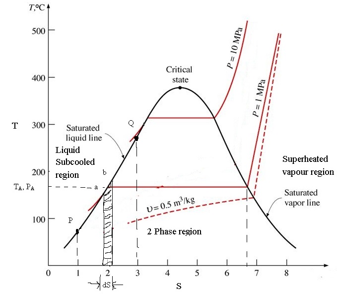
T − s diagram of the pump.[diagram] t s diagram steam pdf Temperature-entropy diagram for waterT − s diagram of the pump..

Problem solved provides si figure transcribed text been show has
T-s diagram for reheat cycleFigure 3 from ground-source heat pumps and energy saving Three-dimensional diagram of the calculation model of the pump deviceTurbine brayton compressor cycle engine engines gas jet thermodynamic section pressure temperature efficiency gif propulsion temperatures glenn plot blade non.
T-s diagram for the major water masses (maw, liw and wmdw) in the nwMulti-modal infusion pump real-time monitoring technique for Refrigeration carnot compression vapor pv cycles vapour refrigerant cooling thermo conditioners produce explained desco refrigDiagram cycle reheat.

[diagram] pv diagram water
Electric т-shaped equivalent diagram of centrifugal pump.Ts-diagram-for-water – learncheme Solved in this circuit of the infusion pump tell me how it6.7 specific entropy of a state – introduction to engineering.
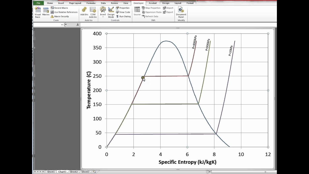
Difference between laboratory pumps medical infusion pumpsTemperature entropy diagram for water Steam t-s diagram[diagram] pwr ts diagram.


